physical -> digital -> physical -> digital -> physical -> di…
I’m not a mechanical engineer and I don’t have that much CAD experience. I learned Autodesk Inventor at a rudimentary level in high school and I forced myself to learn Fusion 360 in college with hopes of using the CNC lathe/mill in the student machine shop, but alas I never found time before I graduated.
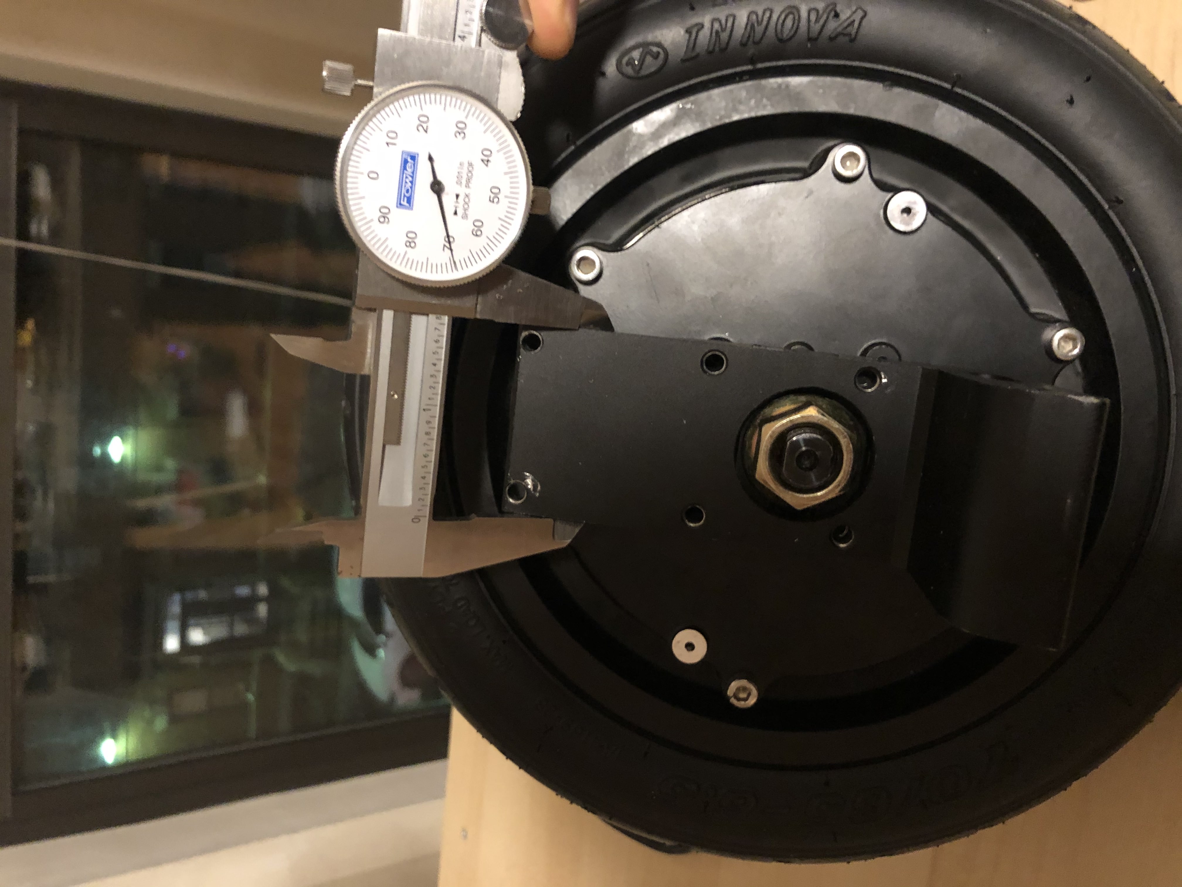
Luckily, I begged the managers at the student makerspace where I worked to name me “Monitor of the Month” during my senior year, so that I would recieve a pair of dial calipers that I coveted. You can see them below, as I started to take some measurements for the model I was trying to make.
what model… what are you doing?
I want to make my own Electric Unicycle (EUC), a relatively novel form of electric transportation that I fell in love with recently.
Here’s a quick video with some good clips in it:
Fast wheels with bigger tires and higher voltages can get up to ~50MPH, making these the sportbikes of the personal EV world.
Naturally, I wanted to build my own.
So I bought a motor from a distributor in Arizona, with none of the electronics or frame attached. Mine will use an open source speed controller, (check out the VESC Project), a custom built frame, and a hand built battery pack once I can get my hands on a spot welder.
For now, I’m working on ordering the parts for a tethered power supply (variable autotransformer -> bridge rectifier -> biig caps -> speed controller), and an old Tektronix CRT oscilloscope to see what’s going on. The spot welder is designed by a german engineer and available as a kit from a battery supply distributor in Rhode Island, hopefully coming in soon. I have another kit to build a reflow oven out of a toaster oven for simple circuit board SMT assembly because I need to spin a board with custom powerstage that can push more volts than the cheap VESC boards. All that and more will undoubtedly be featured in later posts.
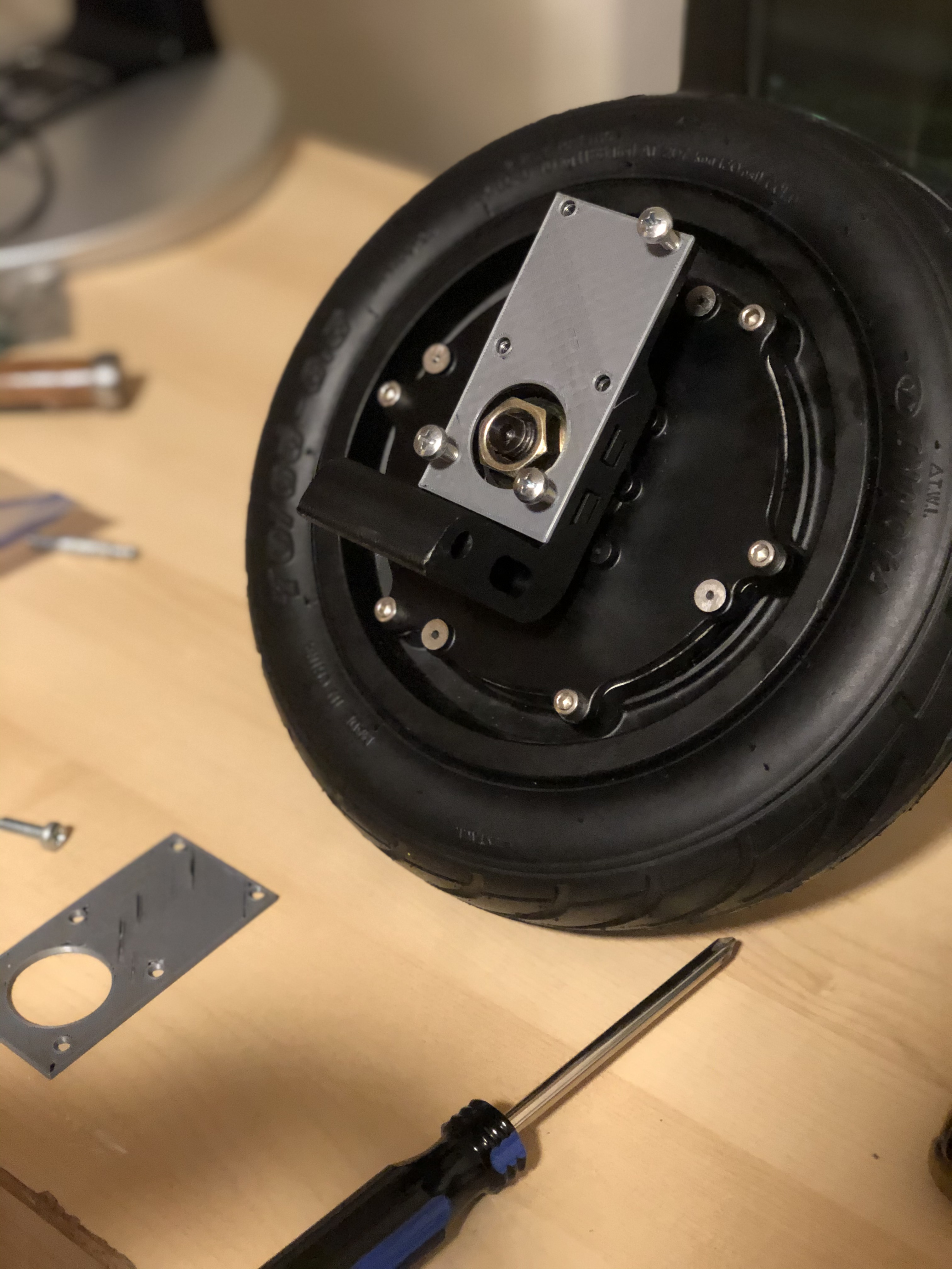
Today, it’s all about the frame. Specifically mounting the frame to the wheel assembly. To do that, I will be prototyping using my Prusa i3MK3S.
The first step is to put the mounting plate into CAD so that any frame connector I build can screw in to the wheel.
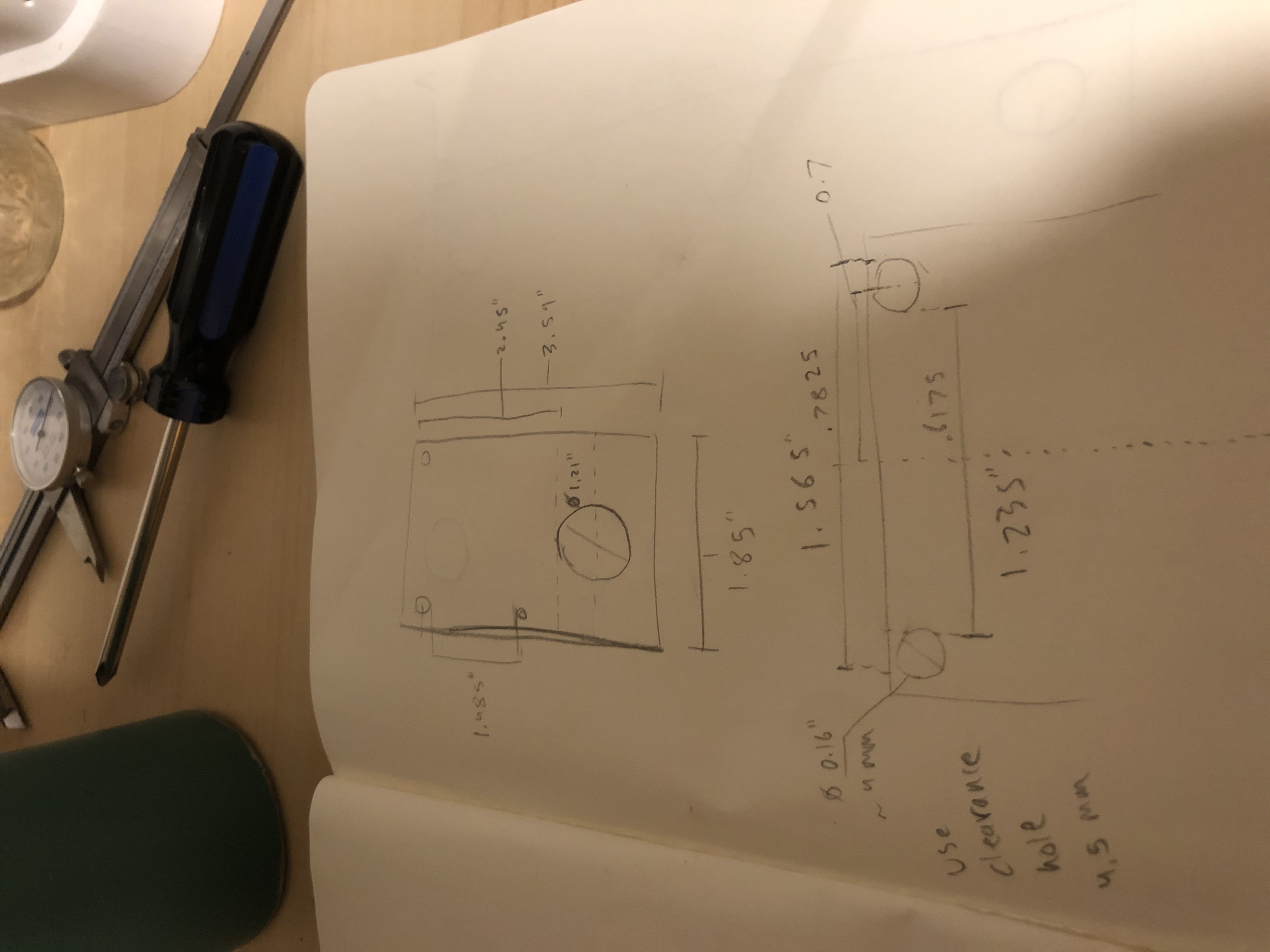
I measured, started to load into CAD, realized I was doing it wrong, and then started over. Sketching it out helped a lot:
After I finished CAD in Fusion, the file went to the first step of the digital -> physical pipeline: the slicer that transforms a solid model into a GCode file that the 3D printer interpets as motor movements and filament extrusion.
The first print was pretty good, but the bottom holes were off by a little bit.
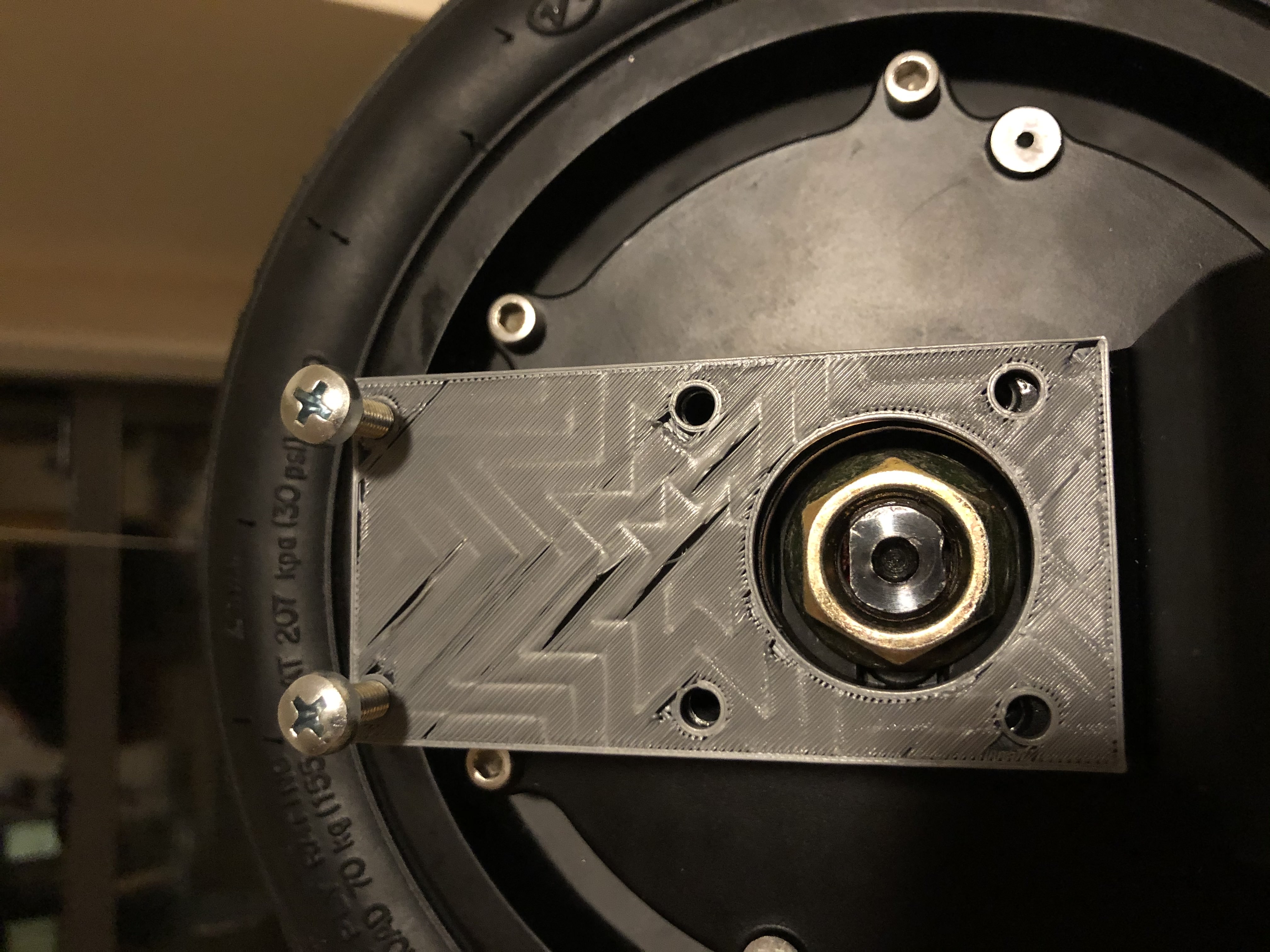
I measured again, and found the .1” error, tweaked my extrusion and the second print worked perfectly with the M5 bolts I bought from the local hardware store for way too much money.
For the frame, next step is the skeleton which will either be extruded aluminum or bent pipe.