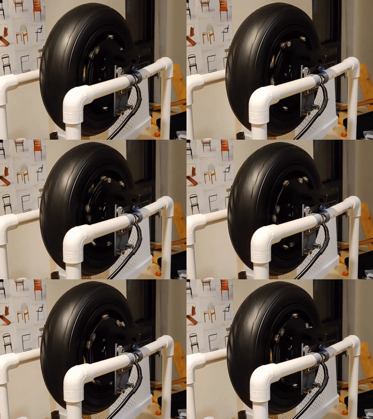
Well, I finally got my motor spinnning!

This is a super big milestone and I’m very excited about it. My EUC project has gone through lots of stops and starts, so sometimes it feels like it stretches out forever. I know from past experience that all big projects have this timeless quality to them, where you cant remember when you started thinking about it or actualizing it, and you can’t fathom an end date.
But the payoffs are rewarding :).
There are three main parts to this, and I will break them out into separate blog posts and link them here.
- The Power Supply
- The Controller
- The Computer
Each of these parts took a ton of planning to figure out what to use, so that I could imagine scaling my workshop and product line. I go into more detail on each part in the linked posts above, but I’d like to use the rest of this post to talk about system design considerations that motivated my choice of component parts.
The EUC project that I’m working on is especially interesting to me because they are performance machines, the kind that push the spec limits of a lot of off-the-shelf components.
Power
Electric motors are often described by their power capabilities. For example, some ebike may have a 500W motor. As you may or may not know, the formula for power is P = IV: Power = I(current) * Voltage.
So a 500W motor could feasibly run on 1 Volt and push 500 Amps, or run on 500 Volts and push 1 Amp. The point is that the power rating is not very descriptive.
There are a number of design considerations that fix these values somewhere in the middle of the ludicrous example I mention earlier. The first thing to remember is that Voltage is proportional to top speed, and I(current) is proportional to torque, or pushing power. For example, a high voltage motor with low current capability may be able to spin insanely fast, but you could easily stop it with your hand. And, on the flip side, a low voltage, high current motor setup will be super powerful but very slow. So a designer must balance these tradeoffs.
Even more than these speed and force constraints, the power of an electric vehicle is highly dependent on the actual power source: batteries!
Batteries are electrochemical systems. Depending on the specific chemistry of the battery type you are using, they will have 3 (at least) important things: cell voltage, capacity, and C rate. The cell voltage is the voltage of 1 battery, and it changes slightly as the battery discharges. Standard Lithium-Ion batteries range from around 4.2 Volts fully charged to around 3.6 Volts when healthily discharged. So the Voltage that you will push through a motor depends on how many batteries you use in series. The capacity of a battery is denoted in mAh (milliAmpHours), and it tells you how much current the battery can output over time. A 3000mAh battery can theoretically supply 3 Amps over the period of an hour. The capacity of a battery pack adds in parallell. A battery pack will be described using two numbers that describe how many batteries are arranged in series, and how many in parallell. So a 10S2P battery pack will have 10 batteries in Series, and 2 in parallell. If the batteries have a nominal voltage of 4.2V and capacity of 3000mAh, the pack will have 42V output and 6000mAh capacity. The third characteristic is the C rate, and it tells you how much current you (safely) can pull out of the battery as a function of capacity (the C). So a 1C battery can discharge 1 times it’s capacity at any instant in time, and a 10C battery can discharge 10 times it’s capacity at any moment. Our imaginary 3000 mAh capacity battery could discharge 3A if it is a 1C cell, or 30A if it’s a 10C cell. The C rate of each cell will apply to the pack as a whole.
So a 500W ebike motor is often powered by a 48V or 54V battery pack, and gets around 10 Amps pushed through it.
Because EUC motors are often a bit bigger, they use 60V-100V packs, and push around the same current, somewhere around 10 Amps.
This takes us back to the system design and the three parts I mentioned. I designed the power supply to be able to handle high voltages and high currents. The highest voltage I could go to is about 140V, and the highest current around 30A. Assuming the wires don’t get hot and start melting, that would be a 4.2kW power supply, strong enough to handle bench testing of almost any light electric vehicle motor I throw at it.
Control
The controller is where things start to choke a bit. A brilliant swedish engineer named Benjamin Vedder created an open source motor controller ecosystem (hardware and software) called VESC. This is perfect for me because a ton of work is already there, and the community is very large. But good quality hardware built on the VESC platform can run you multiple hundreds of dollars. I spent around $50 for a Flipsky MiniFSESC 4.2, but the controller can only function at 60V maximum, which probably won’t be enough for a fast EUC. A custom powerstage is forthcoming :), and you will probably be able to buy those controllers on this website, but thats for another day.
Software
A big reason I chose the VESC platform for my controller is that its super easy to write custom applications that run alongside the motor control loops. This will enable me to put all of the high level balance control on the same processor that runs the actual power conversion to the motor, and save money on components.